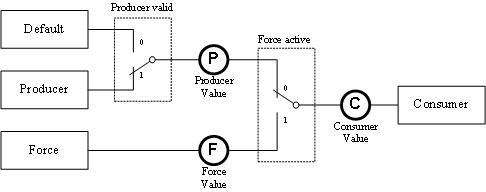
A link node represents the status of a connection between a PV and an I/O point.
Link node variables in PVI can be used for observation (e.g. evaluating the link node status) or monitoring (e.g. displaying data from inputs regardless of the force state). INA2000 data acquisition is a bit slower with link node variables as it is with normal variables (PVs). For this reason, normal variables are the better choice for visualization tasks.
Link node variables can only be used beginning with PLC operating system V2.80 (SG4 Automation Runtime). If the PLC operating system doesn't support link node variables, error 4599 is reported in the PVI variable object.
In the INA2000 line, the data and status of a link node are accessed using INA2000 variable objects. Like global PLC variables, these variable objects must be set up under the CPU object. PVI can be used to access the producer, force, and consumer values of a link node. The following image shows the PVI "pick-up" points within a link node for the producer, force, and consumer values.

Each of the three pick-up points (producer, force, and consumer) are mapped in PVI using a separate variable object. Code letters in the variable object's connection description are used for differentiation. The producer and consumer values can only be read (read-only access). The force value can be both read and written. Link node variables cannot be used as PLC event variables. Otherwise, link node variables behave the same as normal variables (PLC PVs) in PVI.
Connection description syntax:
/RO=<code>+<link_node_name>
or
<code>+<link_node_name>
<code> |
Pick-up point |
P |
Producer value |
F |
Force value |
C |
Consumer value |
The link node name begins with the percent character (%). This is followed by the prefix 'I' (input), 'Q' (output) or 'M' (memory) and the prefix 'X' (1-bit), 'B' (1-byte), 'W' (2-byte), 'D' (4-byte) or 'L' (8-byte) according to IEC IEC 61131-3. The next data point path is separated by a period (.).
If the /RO parameter is specified, the connection description must always be specified in quotation marks ("...") in the object description.
Connection description example:
CD="/RO=C+%IX.SL3.Input10"
Accesses the consumer value of the link node variable "Input10" on slot 3.
Link node status
The status of a link node can be read via all connected variable objects (POBJ_ACC_STATUS access type). Link node variables in the INA2000 line also support status events (POBJ_EVENT_STATUS event type).
The link node status in INA2000 is read together with the link node data. This allows the status to always be as current as the data.
Link node status syntax:
ST=Lkn.<source> FC=<force> UL=<unresolved_link> [IO=<attribute>]
Par. |
Description |
ST |
<source> is used to specify the source of the link node variable's data. "d" .. Default value, "p" .. Producer value, "f" .. Force value Specifying the source depends on the pick-up point being used. |
FC |
<force> is used to specify the force state. 1 .. Force active, 0 .. Force inactive |
UL |
<unresolved_link> signals PV links to the link node. 1 .. At least one PV link present, 0 .. No PV links present |
IO |
<attribute> signals the type of I/O link. "r" .. Link with input, "w" .. Link with output. Simulated I/O modules are identified by an 's'. If the I/O parameter is not specified, there is no I/O link. |
Example of link node status:
ST=Lkn.p FC=0 UL=1 IO=r