A Modbus variable object represents an address range in the process image on the station. These types of objects allow the user to access the channels of the I/O modules on a station, to output statistic values or error counters and to initiate a station restart.
Syntax of connection description:
Single and array variables:
/RO=<variable name>
or
<variable name>
Element of an array variable:
/RO=<variable_name>[<index>]
or
<variable_name>[<index>]
If the variable name is defined as the /RO parameter, the connection description must always be specified in quotation marks ("...") in the object description. This name can be a defined variable, generic variable or a register address in the process image. These are not case-sensitive.
Param. |
Value |
Settings |
Description |
/RO |
Variable name |
None |
Value: "/RO=Heating" |
/VT |
Data type |
None |
Value: "/VT=u16" |
/VN |
Number of elements |
1 |
Value: "/VN=1" |
/US |
Attribute |
rw |
Value: "/AT=rw" |
Connection description examples:
CD="/RO=Heating"
CD=DO[2]
CD="/RO=0x2400 /VT=u16 /AT=rw"
Defined variables
The defined variables are loaded from a configuration file when setting up a station. This configuration file is created in the AS configurator and contains the assignments of symbolic names for the corresponding register addresses in addition to the configuration of the bus controller and the modules. The data format of these pre-defined variables (i.e. data type, element number and attribute) is also determined in this configuration and cannot be changed by the user.
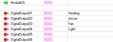
The symbolic names are specified in the I/O assignment of the AS configurator as shown in the following figure.

Therefore, the only thing left to do when setting up a variable object is to specify this symbolic name in the connection description (e.g. CD=Heating).
Generic variables
Some variables are automatically defined when setting up a station object if a connection with the hardware was able to be established. These variables are the cyclic data of the I/O modules stored in the process image. The variables are stored as array variables and their element number is determined by the type and number of modules present on the bus.
When setting up objects for generic variables, only the name with optional element index has to be specified (e.g. CD=AI or CD=DO[2]).
RO |
FT |
Description |
AI |
U16 |
Analog input register |
AO |
U16 |
Analog output register |
DI |
U8 |
Digital input register |
DO |
U8 |
Digital output register |
NS |
U16 |
Network status |
OS |
U16 |
Output status |
Process image
The following table lists the memory areas in the process image with the permissible data types and access types for the corresponding address range. Refer to the bus controller specification to find out exactly how the individual memory areas are structured. Memory areas are automatically initialized and addresses are automatically assigned to the variables when operating a station with a configuration file.
Therefore, variables must only be set up using a memory address when operating a station without configuration or when setting up or changing the configuration from the software.
When setting up an object via the address, the correct address is required and the data format must be specified with data type, element number and attributes (e.g. CD="/RO=0x2400 /VT=u16 /AT=rw"). When setting up an object, the specified parameters are checked for validity and any occurring errors are reported. The address can be specified as a decimal or hexadecimal value.
RO |
FT |
AT |
Comment |
0x00000-0x007FF |
U16, I16, U32, I32 |
r |
Analog inputs |
0x00800-0x00FFF |
U16, I16, U32, I32 |
rw |
Analog outputs |
0x01000-0x01FFF |
U16, I16, U32, I32 |
rw |
System parameters |
0x02000-0x023FF |
U16, I16, U32, I32 |
r |
Digital inputs (word-oriented) |
0x02400-0x027FF |
U16, I16, U32, I32 |
rw |
Digital outputs (word-oriented) |
0x02800-0x029FF |
U16, I16 |
r |
X2X network status |
0x02A00-0x02BFF |
U16, I16 |
r |
Output status |
0x0A000-0x0AFCF |
U16, I16, U32, I32 |
rw |
Module data sorted by index |
0x0B000-0x0BFFF |
U16, I16, U32, I32 |
rw |
Module data sorted by parameter |
0x0C000-0x0DFFF |
U16, I16, U32, I32 |
rw |
Module configuration |
0x10000-0x11FFF |
U8, I8, U16, I16, U32, I32, BOOLEAN |
r |
Digital inputs (bit-oriented) |
0x20000-0x21FFF |
U8, I8, U16, I16, U32, I32, BOOLEAN |
rw |
Digital outputs (bit-oriented) |